Overloaded outlets or extension cables might provide a fire hazard. If in doubt, use a reference book or hire an expert to do the task. While you may believe you completed the process correctly, a single error might leave a potential fire threat lurking in your wall space. A professional electrician is knowledgeable about all aspects of house wiring and may be able to securely wire your home faster than you can learn.
In each scenario, thoroughly review the manufacturer's paperwork prior to initiating the keypad installation, which should typically occur during the trim-out process. On the inside circuit board of certain keypad devices, there may be a user interface connection that takes a strip connector with up to 12 wire locations. Examine the wiring schematics to see if this is the correct wiring strategy for connecting the keypad to the remote trigger, panic, or other relay outputs or inputs. Electrical wire no bigger than 16 AWG should be utilized to link the keypad to its power supply and, if applicable, a door strike. To connect the keypad to the home security system controller for relay signals out or in, either unshielded twisted-pair (UTP) or shielded twisted-pair (STP) wire is utilized.
We recommend using a two-core wire with a diameter more than 0.22mm2 for the cable connecting the Door Contact to the Controller. If you do not need additional features, such as monitoring the door status online or alerting you if the door is left open for an extended period of time or if a break-in occurs, the door contact cable may be removed. Cable de communication: (from the controller to controller, controller to computer)
29+ Photos of Wiring Star Delta Motor 3 Phase The windings are arranged in such a way that they generate a revolving magnetic field. We must wire this formula. from www.electricaltechnology.org: Star Delta Starter Y D Starter Power Control Wiring Diagram A star delta starter is a kind of motor starter that operates a three-phase motor in star configuration during startup. Numerous motors may be connected for both high and low voltages, as well as delta or wye configurations (sometimes called y or star wiring). In this video, we demonstrate how to connect a three-phase motor's six wire star delta connector. english Hello everyone, in this video, I will demonstrate how to wire a star delta motor with a running motor. I previously shown how to wire a star delta motor with a running motor in earlier videos. (10) Wiring for power and control: The star connection connects the comparable ends (start or finish) of the three windings.
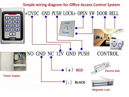
Door Access Control System Wiring Diagram Pdf
Toyota Alphard is a five-door class L minivan with five doors. In December 2017, a restyled version of the third generation of the vehicle was unveiled. The vehicle became available for purchase in 2018. Toyota Auris is a five-door hatchback classified as a Class C vehicle. A restyled version of the Toyota Auris's second generation. The automobile had its world premiere at the 2015 Geneva Motor Show.
This article will walk you through the process of installing a simple RFID and password-based access control system. Access control systems ensure that only authorized individuals are permitted to enter or depart the premises. Locks, turnstiles, biometric readers, facial recognition readers, RFID readers, and boom barriers are all examples of access control systems. The following materials are necessary for this project:
Additionally, a microcontroller paired with a digital switch minimizes the cost of connecting a nearby digital camera and digital intercom. The connection to the microcontroller is reduced to two wires (Ethernet and power), with the option of power over Ethernet depending on the setup. Microcontrollers should always be mounted on the secure side of the door, never on the vulnerable side. Nota bene: One company, whom I otherwise like, produces a microcontroller with an integrated card reader, which allows for the microcontroller to be mounted in a j-box at waist height on the insecure side of the door. These should be used with great care, since removing the card reader immediately provides access to the lock's power, and hence the ability to open the door from the insecure side using just hand tools. Needless to say, they should never be used on outside doors.
Door Access Control System Connection Diagram
A RFID-enabled door lock or access control system is built around a few simple ideas. In our system, we save a collection of RFID card data, say three or ten RFID card data. Access will be allowed when the individual with the appropriate RFID card (compatible with the data packed in our program/system) comes and swipes his RFID tag. When a person swipes his RFID tag with the incorrect RFID card (whose data is not loaded in our system), access is prohibited. I hope you grasp the RFID-based Door Lock's system idea. Above is the complete circuit schematic for connecting the RFID module to the 8051. The circuit reads the RFID card's unique ID code and displays it on the 162 LCD display. The RFID module's Tx pin is linked to the microcontroller's Port 3.5. This channel is used by the microcontroller to receive data from the RFID module. The reset circuit is composed of the switch S1, the capacitor C1, and the resistor R1. The reset circuit is comprised of capacitors C2, C3, and crystal X1.
The advantages include straightforward training and value-added services such as attendance. The cost is quite inexpensive, and the networking is self-contained and will not be impacted by other devices' shared network. Suitable for projects involving a big number of people, a high level of mobility, and a large number of doors access control systems. Disadvantages: high cost, difficulties of installation and maintenance, a small network size (usually less than 1000 units), the more devices, the more sophisticated the network, the more interference. The network's range is restricted, often to a few hundred meters.
Additionally, a microcontroller paired with a digital switch minimizes the cost of connecting a nearby digital camera and digital intercom. The connection to the microcontroller is reduced to two wires (Ethernet and power), with the option of power over Ethernet depending on the setup. Microcontrollers should always be mounted on the secure side of the door, never on the vulnerable side. Nota bene: One company, whom I otherwise like, produces a microcontroller with an integrated card reader, which allows for the microcontroller to be mounted in a j-box at waist height on the insecure side of the door. These should be used with great care, since removing the card reader immediately provides access to the lock's power, and hence the ability to open the door from the insecure side using just hand tools. Needless to say, they should never be used on outside doors.
At screencheck, we adhere to a compliant security-based architecture for our customers' door access restrictions. We are industry leaders in this sector due to our relevant experience in offering cutting-edge security solutions. Our end-to-end solution ensures that no stone is left unturned in terms of access security and control, which results in delighted and happy customers. Check out our solutions and pay a visit to our Dubai headquarters if you want to put your business ahead of the curve when it comes to employee access control. Access control products may be found here.
Door Entry System Wiring Diagram
Most, if not all, coverings snap on to reveal the internal chime. To remove, â â â â â â â â â â 2) Push-Button: The chime is activated using momentary switch buttons. Consider the following: you could remove the switch and manually connect the two open ended wires, thereby completing the electrical circuit necessary to trigger the chime. When the switch is added, it does the same purpose, temporarily completing the electrical circuit to power the chime and then breaking it when the switch is released, since the internal contacts no longer connect.